|
Technical Data
|
|
Voltage inputs
|
|
Number of inputs
|
4 (3 phase + neutral) dc-coupled
|
|
Maximum input voltage
|
1000 Vrms
|
|
Nominal voltage range
|
Selectable 1 V to 1000 V
|
|
Max. peak measurement voltage
|
6 kV (transient mode only)
|
|
Input impedance
|
4 MΩ//5 pF
|
|
Bandwidth
|
> 10 kHz, up to 100 kHz for transient mode
|
|
Scaling
|
1:1, 10:1, 100:1, 1,000:1 10,000:1 and variable
|
|
Current inputs
|
|
Number of inputs
|
4 (3 phase + neutral) dc- or ac-coupled
|
|
Type
|
Clamp or current transformer with mV output or i430flex-TF
|
|
Range
|
0.5 Arms to 600 Arms with included i430flex-TF (with sensitivity 10x)
5 Arms to 6000 Arms with included i430flex-TF (with sensitivity 1x)
0.1 mV/A to 1 V/A and custom for use with optional ac or dc clamps
|
|
Input impedance
|
1 MΩ
|
|
Bandwidth
|
> 10 kHz
|
|
Scaling
|
1:1, 10:1, 100:1, 1,000:1 10,000:1 and variable
|
|
Sampling system
|
|
Resolution
|
16 bit analog to digital converter on 8 channels
|
|
Maximum sampling speed
|
200 kS/s on each channel simultaneously
|
|
RMS sampling
|
5000 samples on 10/12 cycles according to IEC61000-4-30
|
|
PLL synchronization
|
4096 samples on 10/12 cycles according to IEC61000-4-7
|
|
Nominal frequency
|
434-II and 435-II: 50 Hz and 60 Hz
437-II: 50 Hz, 60 Hz and 400 Hz
|
|
Display modes
|
|
Waveform display
|
Available in all modes via SCOPE key
435-II and 437-II: Default display mode for Transients function
Update rate 5x per second
Displays 4 cycles of waveform data on screen, up to 4 waveforms simultaneously
|
|
Phasor diagram
|
Available in all modes via Scope waveform display
Default view for Unbalance mode
|
|
Meter readings
|
Available in all modes except Monitor and Transients, provides tabulated view of all available readings
Fully customizable up to 150 readings for Logger mode
|
|
Trend graph
|
Available in all modes except Transients
Single vertical cursor with min max and avg reading at cursor position
|
|
Bar graph
|
Provides 50/60** cycles of waveform information and associated 1/2 cycle rms values for Volts and Amps
|
|
Measurement modes
|
|
Scope
|
4 voltage waveforms, 4 current waveforms, Vrms, Vfund. Arms, A fund, V @ cursor, A @ cursor, phase angles
|
|
Volts/amps/hertz
|
Vrms phase to phase, Vrms phase to neutral, Vpeak, V Crest Factor, Arms Apeak, A Crest Factor, Hz
|
|
Dips and swells
|
Vrms½, Arms½, Pinst with programmable threshold levels for event detection
|
|
Harmonics dc, 1 to 50, up to 9th harmonic for 400 Hz
|
Harmonics Volts, THD, Harmonic Amps, K factor Amps, Harmonic Watts, THd Watts, K factor Watts, Interharmonic
Volts, Interharmonic Amps, Vrms, Arms (relative to fundamental or to total rms)
|
|
Power and energy
|
Vrms, Arms, Wfull, Wfund., VAfull, VAfund., VAharmonics, VAunbalance, var, PF, DPF, CosQ, Efficiency factor, Wforward, Wreverse
|
|
Energy loss calculator
|
Wfund, VAharmonics, VAunbalance, var, A, Loss Active, Loss Reactive, Loss Harmonics, Loss Unbalance, Loss Neutral, Loss Cost (based upon user defined cost / kWh)
|
|
Inverter efficiency (requires optional dc current clamp)
|
Wfull, Wfund, Wdc, Efficiency, Vdc, Adc, Vrms, Arms, Hz
|
|
Unbalance
|
Vneg%, Vzero%, Aneg%, Azero%, Vfund, Afund, V phase angles, A phase angles
|
|
Inrush
|
Inrush current, Inrush duration, Arms½, Vrms½
|
|
Monitor
|
Vrms, Arms, harmonic Volts, THD Volts, PLT, Vrms½, Arms½, Hz, dips, swells, interruptions, rapid voltage changes, unbalance and mains signalling.
All parameters are measured simultaneously in accordance with EN50160 Flagging is applied according to IEC61000-4-30 to indicate unreliable readings due to dips or swells
|
|
Flicker (435-II and 437-II only)
|
Pst(1min), Pst, Plt, Pinst, Vrms ½, Arms ½, Hz
|
|
Transients (435-II and 437-II only)
|
Transient waveforms 4x Voltage 4x Amps, triggers: Vrms ½, Arms ½, Pinst
|
|
Mains Signaling (435-II and 437-II only)
|
Relative signaling voltage and absolute signaling voltage averaged over three seconds for up to two selectable signaling frequencies
|
|
Power Wave (435-II and 437-II only)
|
Vrms½, Arms½ W, Hz and scope waveforms for voltage amps and watts
|
|
Logger
|
Custom selection of up to 150 PQ parameters measured simultaneously on 4 phases
|
|
General specifications
|
|
Case
|
Design Rugged, shock proof with integrated protective holster
Drip and dust proof IP51 according to IEC60529 when used in tilt stand position
Shock and vibration Shock 30 g, vibration: 3 g sinusoid, random 0.03 g 2 /Hz according to MIL-PRF-28800F Class 2
|
|
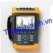
Display
|
Brightness: 200 cd/m 2 typ. using power adapter, 90 cd/m 2 typical using battery power
Size: 127 mm x 88 mm (153 mm/6.0 in diagonal) LCD
Resolution: 320 x 240 pixels
Contrast and brightness: user-adjustable, temperature compensated
|
|
Memory
|
8GB SD card (SDHC compliant, FAT32 formatted) standard, upto 32GB optionally
Screen save and multiple data memories for storing data including recordings (dependent on memory size)
|
|
Real-time clock
|
Time and date stamp for Trend mode, Transient display, System Monitor and event capture
|
|
Environmental
|
|
Operating temperature
|
0 °C ~ +40 °C; +40 °C ~ +50 °C excl. battery
|
|
Storage temperature
|
-20 °C ~ +60 °C
|
|
Humidity
|
+10 °C ~ +30 °C: 95 % RH non-condensing
+30 °C ~ +40 °C: 75 % RH non-condensing
+40 °C ~ +50 °C: 45 % RH non-condensing
|
|
Maximum operating altitude
|
Up to 2,000 m (6666 ft) for CAT IV 600 V, CAT III 1000 V
Up to 3,000 m (10,000 ft) for CAT III 600 V, CAT II 1000 V
Maximum storage altitude 12 km (40,000 ft)
|
|
Electro-Magnetic-Compatibility (EMC)
|
EN 61326 (2005-12) for emission and immunity
|
|
Interfaces
|
mini-USB-B, Isolated USB port for PC connectivity
SD card slot accessible behind instrument battery
|
|
Warranty
|
Three years (parts and labor) on main instrument, one year on accessories
|
|
Phase angle Measurement range:
|
-360° … +360°
|
|
Included accessories
|
|
Power options
|
BC430 Power Adapter
International plug adapter set
BP290 (Single capacity Li-ion battery) 28Wh (7 hours or more)
|
|
Leads
|
TL430 Test lead and Alligator clip set
|
|
Color coding
|
WC100 color coding clips and regional decals
|
|
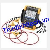
Flexible current probes
|
i430flex-TF, 24 inch (61cm) length, 4 clamps
|
|
Memory, Software and PC connection
|
8 GB SD card
PowerLog on CD (includes operator manuals in PDF format)
USB cable A-Bmini
|
|
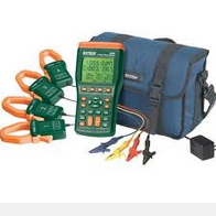
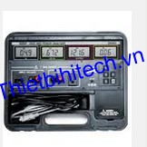
Carrying case
|
C1740 Soft Case for 434-II and 435-II
C437 Hard Case with rollers for 437-II
|